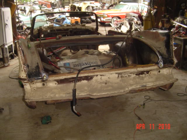
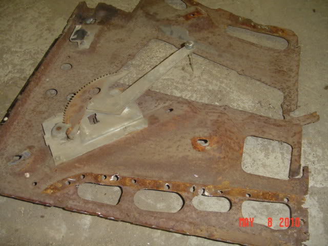
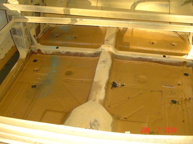
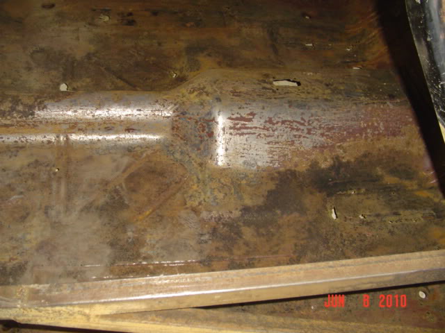
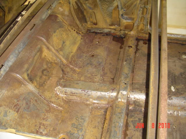
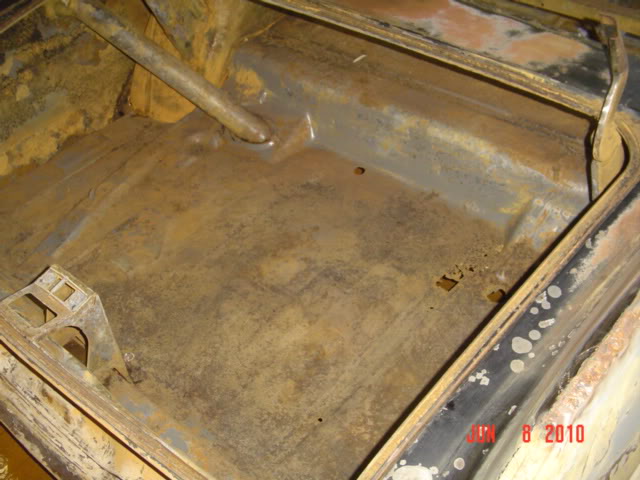
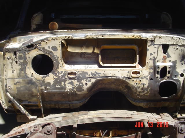
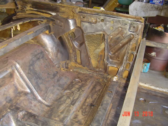
John (Big M), Here are some pictures of my convert. I took pics of the passenger and drives side leading edge of the inner wheel well hump. Hopefully it encompasses what are you need me to take measurements of.
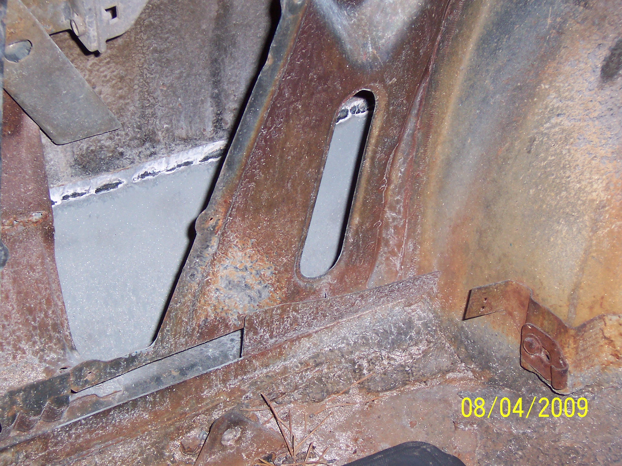
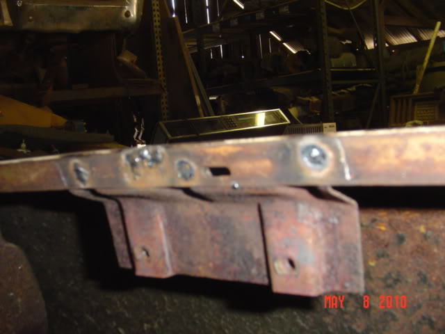
Now, Only being in the 59 Plymouth world for 4 years, I thought the extra Convertible X “frame to body” outrigging was the one that goes just under the seat frame reinforcement plate that is on the underside of the floor body, mine are rusty, but you can see a square (sorta square) support that goes down from the seat frame extra support bracket and picks up this extra bracing from the frame to support the floor seat area, thereby giving it some extra rigidity to body.There is one more support that spans to the X frame point too that is different from a HT.
Well Instead of guessing I looked in the 57-58 Plymouth Service manual and on page 136 and 137 they show that there is two extra bracing points on each side of an convertible (4 total) that is not on the HT version. One inboard and one outboard of the outer frame logitudital to give extra strength to the Convert body shell. Look at the convert frame dimensions (page 137) and you will see that at the location point that is from the front part of the frame 72 25/32 inch and the 77 23/32 inch point of the frame layout the special convertible support points.
Hope that helps, I will take measurements of any part for you to fab up. If you can circle the area I will take better closer pictures of it.
Damn John Q. - I thought my car was a mess, compared to yours mine is a piece of cake. I really admire you for taking on such a project. As roger said about my car, I don’t know if I would do it. Wish you all the luck in the world. When you finish it maybe we should meet in Nawlins and get some Seafood Gumbo and a Roast Beef Po Boy Samich, after all we will need to build our strength back up.
Dick.
Hey John Fwolie,
I am happy to see a new post from you. I know winter time is slow for all of us.
Sure, your convertible is a MAJOR project, but you have never allowed that you were intimidated by the job, therefore I am sure you can make this one come together.
-roger-
The weather this weekend was not conducive to any outdoor activities, so I labored away on Rusty some more.
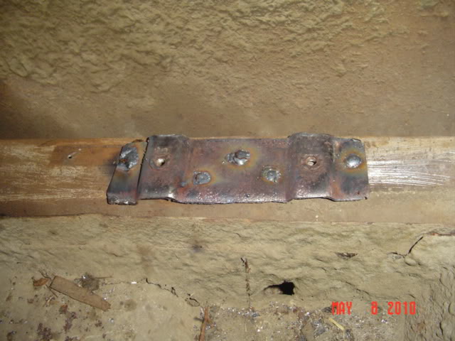
After cleaning up any of the mating surfaces, I located the lead seam where the front will be connected to. Heat from a brazing torch made the lead flow out, and I drilled out the spotwelds.
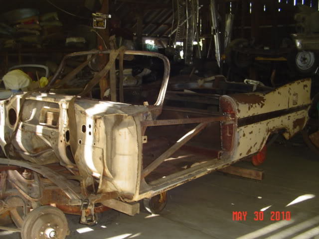
Going together- This took two people to position onto the body. Slug-[Rodger] was a big help here. The rear corners were brazed [as per factory] and a series of clamps kept the body alignment in check.
Mig welding the drilled out spotwelds, these will later be ground off flush. One problem I ran into was that the driver’s side quarter panel wanted to moilcan inwards when the top seam was pinched together, after much consideration, I remembered the RH quarter on the original convertible had taken a hit at one time, and was tweaked. I found a bit of secondary damage on the deck panel, where the metal was pushed upwards. A bit of hammer and dolly work allowed it to settle back into place, and the left quarter panel no longer wanted to contract. Thank goodness!
John, great work on mating the two cars together and saving a valuable convert. Your attention to detail will pay off.
Dick, the interior of my car (other then the floors) just had surface patenia that all has been neutralized and removed. Not as bad as you think it is. (I hope…)
My Bad, this is John Fowlie’s thread. I will take a time out for my bad manners!
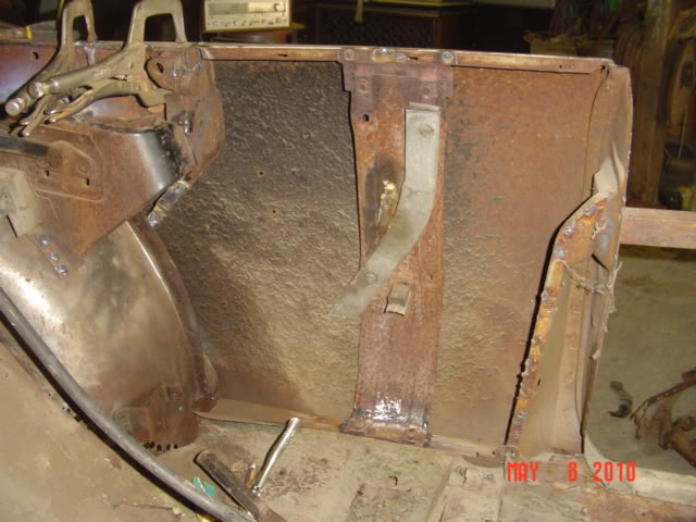
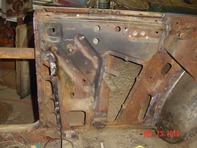
I finished positioning and welding the stands and braces, these will just need a final grinding, to be done once the body is assembled and on a rotisserie. Looks like things are lining up the way they should, so it will be on to the next step.
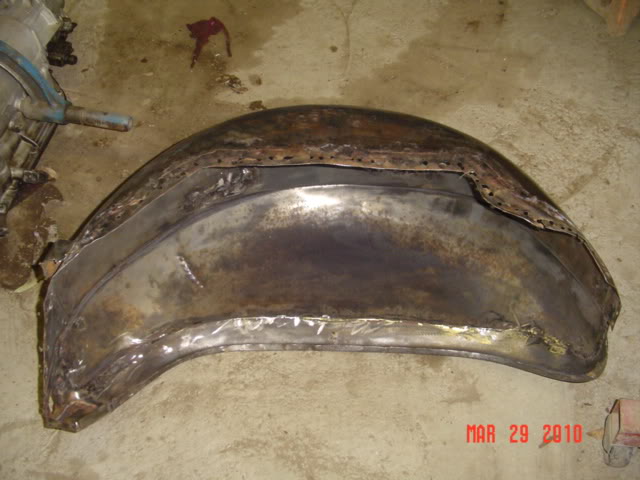
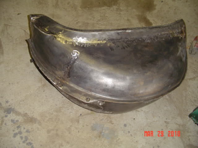
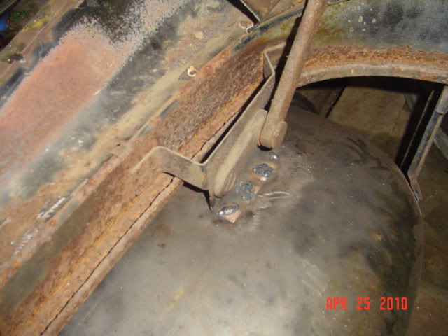
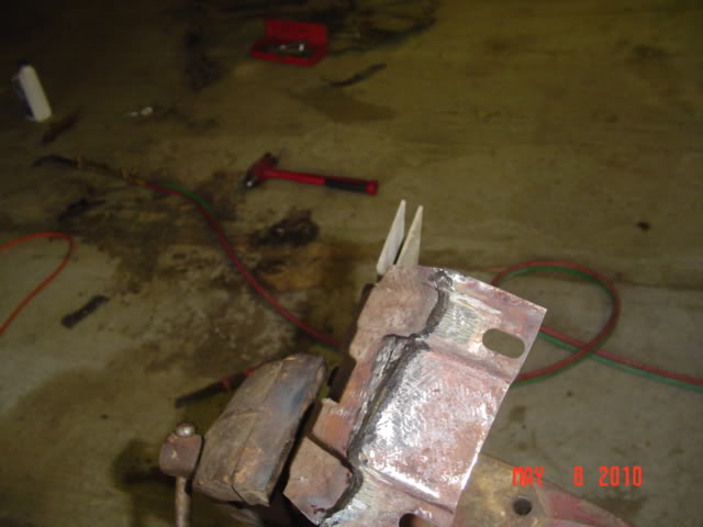
This is what I had to make for both sides. These are drains for the convertible top well, they channel the water away from the upholstered surfaces in the rear seat area. The one shown here is from the driver’s side. The passenger side one was non-existent!
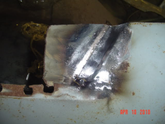
Here I am fitting the left one on to the piece that will be welded to the convertible frame assembly. I used brass rod to fasten these, as the original piece they would be welded to was weakened by rust, but not bad enough to redo. Welding with a mig would probably burn through-
I got the left side quarter window frame and supports completed. Spent two hours just to determine where the main support runner that holds the vertical window guide in place situated. The DeSoto uses different quarter windows, so it was of little help here. Luckily I saved the remains of the quarters I had cut off long ago, hopefully my measurements are correct here.
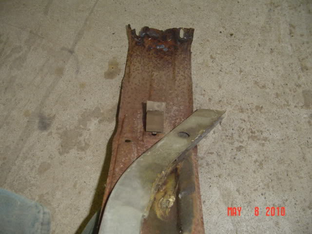
This is the main vertical support, the bottom had just a bit left, and thepiece it fastened too was pretty far gone. I removed the 2-door hardtop window stop, as the mount for the support would need to go in its place.
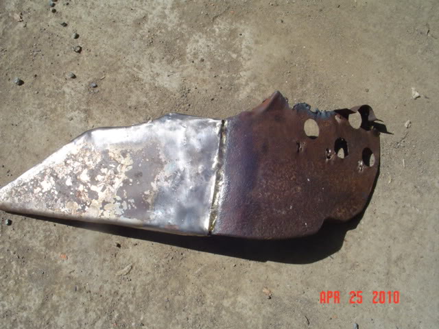
The rear piece, along with a replacement I made, it’s hard to tell in the photos, but this piece requires a strange compound curve, and is stamped from the factory. I used blacksmithing techniques to get a replacement piece fairly close-
I got the passenger side all rebuilt and installed, no need to show a ton of photos, since it was similar to the work on the driver’s side. Coming soon, the ‘Big Dip’ experiment.
John - My hat is off to you, you are and inspiration, I’ll never again complain about how bad my car was or how much bondo was in it. I know sometimes like me, you probably say “what for” but I try to keep my mind focused on what the finished product will look like and know the pain in the ass thing I’m doing right now will be over and never have to be done again. When ever I take a negative attitude I look at your work and reliaze I don’t have it so bad.
Dick.
John,
With your vast and ongoing experience, can you saywhat would be involved, heck, could it be even feasible to adjust my “flattened” hardtop wheel wells to more reasonably resemble the cvt wheelwells? It has long bothered me that my car’s top won’t fold down as far as it should.
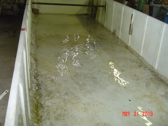
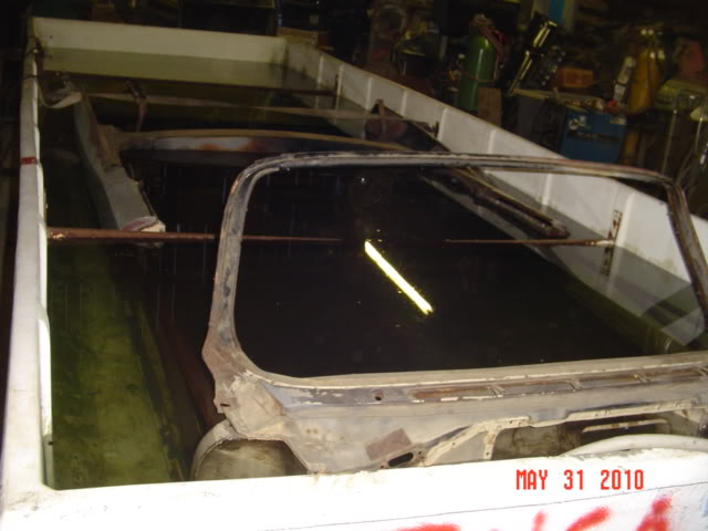
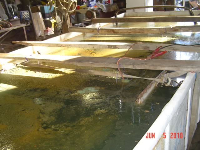
After setting it in place, the bin was washed out, and sealer was used on any obvious leakage points. Two of the cross braces required removal in order to set the body in.
About eight inches of water was added, and any additional leaks found were sealed with wet patch. Then the body was lowered into the bin, while the hose ran constantly. One brace was reinstalled, as well as a trucker’s strap, as the pressure would be too much for the walls to hold without them.
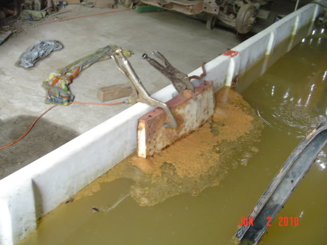
Baking soda [lots of it] was mixed in, and power to the anode [junk exhaust pipes] and ground to the cathode [body] was introduced. After an hour the water had changed from clear to a pale green-
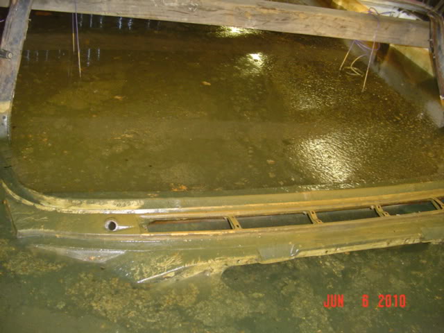
Rooting through the scrap pile the next day, I used two old store gondola shelves, and tied them together with a copper cable. These I could rotate around the car body when needed. After another full day, results were noticeable in the rusty color of the water in the bin.
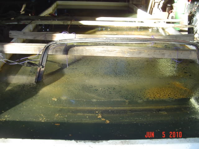
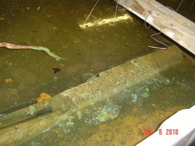
The water gets murkier and murkier each day. For the final 48 hours, a series of grids were hung just above the floorboards and trunk floor. Here, the electrolyte was allowing 40 amps to pass through it.
Time to drain the bin. I used a piece of garden hose to slowly empty the container, revealing an enormous amount of rust, sludge, and crud that was removed from the body. Remember, the body was blown out with air pressure, and scraped before submerging it.
A fin slowly reappears from the muck-
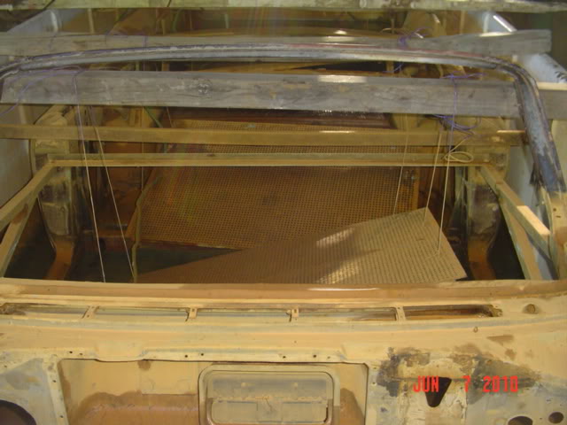
After wirebrushing the floorboards, I can see exactly what sections will need to be replaced. There are several weak areas that did not look bad before all the rust was lifted away. It will be nice working with clean metal, however. Interesting also how the paint and undercoating came off in certain areas, poor adhesion?